Set, Clear, Toggle, and Check Bit Value in C
In the embedded system design, the system needs to check the input state and then send signals to other devices or change the state of the outputs. Since each GPIO pin is connected to a different device (some pins are input, and other pins may be output or other functions), it is impossible to check the pin state by comparing it with a constant value. The setting, clearing, and toggling pins also have the same situation: constant values can not be assigned directly to the port DATA register because each GPIO pin is associated with the corresponding bit in the port DATA register; a bitwise operation can be used to solve these issues.
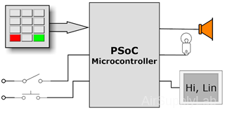
Figure 1: Example of Embedded System
Bit Masks
Definition:
A bit mask is a binary number used to select or manipulate specific bits within another binary number. This is achieved through bit-wise operations such as AND, OR, and XOR. Each bit in the mask determines whether the operation will affect the corresponding bit in the target value.
- Mask 1:
- A bit mask where the bit of interest is set to 1 and all other bits are set to 0.
- Used to isolate, set, or toggle a specific bit.
- Example: To isolate bit 3, mask1 = 0b00001000, or mask1 = 0x08.
- Mask 0:
- A bit mask where the bit of interest is set to 0 and all other bits are set to 1.
- Used to clear a specific bit.
- Example: To clear bit 3, mask0 = 0b11110111, or mask0 = 0xF7.
- Converting Between Mask 1 and Mask 0 Values:
- To convert a Mask 1 value to a Mask 0 value, invert all the bits of the Mask 1 value. Conversely, to convert a Mask 0 value to a Mask 1 value, invert all the bits of the Mask 0 value
- Bit-wise NOT Operator (~):
- Convert Mask 1 to Mask 0:
#define MASK1 0x08 // 0b00001000 #define MASK0 ~(MASK1) // 0b11110111 - Convert Mask 0 to Mask 1:
#define MASK0 0xF7                  // 0b11110111
#define MASK1 ~(MASK0)              // 0b00001000
- Convert Mask 1 to Mask 0:
Types of Masks:
- Single Bit Masks:
- Masks that target a single bit.
- Example:
#defien _PIN0   0x01
#defien _PIN1   0x02
#defien _PIN2   0x04
#defien _PIN3   0x08
#defien _PIN4   0x10
#defien _PIN5   0x20
#defien _PIN6   0x40
#defien _PIN7   0x80
- Multi-Bit Masks:
- Masks that target multiple bits.
- Example:
#defien _LOPINS     (_PIN3 | _PIN2 | _PIN1 | _PIN0)
#defien _HIPINS     (_PIN7 | _PIN6 | _PIN5 | _PIN4)
Summary:
A bit mask in embedded systems is a powerful tool for manipulating individual bits within a register or variable. Using bit-wise operations with carefully designed masks, programmers can set, clear, toggle, and check specific bits, enabling precise control over hardware behavior.
Bit-wise Operators in Embedded Programming
Bit-wise operators are crucial for manipulating individual bits within registers and variables in embedded programming. These operators allow precise control over hardware, enabling efficient and low-level operations.
Setting bits to 1
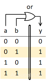
Figure 2: Truth Table for Bitwise-OR
$n: = 0\;or\;1\quad \Rightarrow \left\{ \begin{array}{l} n|0 = n & \to {\rm{same as }}n{\rm{ value}}\\ n|1 = 1 & \to {\rm{always be 1}} \end{array} \right.$
To turn certain bits on, the bitwise-OR operation can be used, following the principle that n OR 1 = 1 and n OR 0 = n. Therefore, to make sure a bit is on, OR can be used with a 1. To leave a bit unchanged, OR is used with a 0.
- A bit "mask 1" can be used to set specific bits to 1.
- This is commonly done using the bit-wise OR operation.
- Examples:
- Setting 1 on bits 5 and 3, the other bits are unchanged.
#define MASK1 0x28 // 0b00101000 uint8_t REG = 0x4E; // 0b01001110 REG = REG | MASK1; // REG is now 0x6E (0b01101110) - To set the 3rd bit of an 8-bit register.
#define BIT3_MASK1 0x08 // 0b00001000 uint8_t REG = 0xA3; // 10100011 in binary REG = REG | BIT3_MASK1; // REG is now 0xAB (10101011 in binary) - To light on the lamp connected to PB2, bit 2 of the Port B DATA register needs to be set to 1.
The following expression shows how to set bit 2 to 1:
PORTB->DATA = PORTB->DATA | _BIT2;
// or
PORTB->DATA |= _BIT2;
- Setting 1 on bits 5 and 3, the other bits are unchanged.
Clearing bits to 0
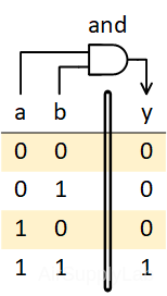
Figure 4: Truth Table for Bitwise-AND
$n:0\;or\;1\quad \Rightarrow \left\{ \begin{array}{l} n\& 0 = 0 & {\rm{always be 0}} & \\ n\& 1 = n & {\rm{same as }}n{\rm{ value}} \end{array} \right.$
From the above results, you can find that when a bit is ANDed with a 0, the result is always 0, i.e. n AND 0 = 0. To leave the other bits as they were originally, they can be ANDed with 1, since n AND 1 = n.
- A bit "mask 0" can be used to clear specific bits to 0.
- If a "mask 1" value is used, convert it to a "mask 0" value using the inverter operator (~).
- This is commonly done using the bit-wise AND operation with a "mask 0" value.
- Example:
- Clearing on bits 5 and 3, the other bits are unchanged.
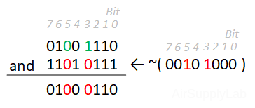
#define MASK0 0xD7 // 0b11010111 #define MASK1 0x28 // 0b00101000 unsigned char REG = 0x4E; // 0b10111110 REG = REG & MASK0; // REG is now 0x46 (01000110 in binary) // or REG = REG & ~(MASK1); // REG is now 0x46 (01000110in binary) - To clear the 3rd bit of an 8-bit register
#define BIT3_MASK0 0xF7 // 0b11110111 #define BIT3_MASK1 0x08 // 0b00001000 unsigned char REG = 0xAB; // 10101011 in binary REG = REG & BIT3_MASK0; // REG is now 0xA3 (10100011 in binary) // or REG = REG & ~(BIT3_MASK1); // REG is now 0xA3 (10100011 in binary) - To turn off the lamp connected to PB2, bit 2 of the Port B DATA register needs to be clear to 0.
The following expression shows how to clear bit 2 to 0:
PORTB_>DATA = PORTB & ~(_BIT2);
PORTB->DATA &= ~(_BIT2);
- Clearing on bits 5 and 3, the other bits are unchanged.
Toggling bit values
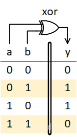
Figure 6: Truth Table for Bitwise-XOR
$n:0\;or\;1\quad \Rightarrow \left\{ \begin{array}{l} n\^0 = n & {\rm{same as }}n{\rm{ value}} & \\ n\^1 = \bar n & {\rm{invertted }}n{\rm{ value}} \end{array} \right.$
We discussed how to turn bits on and off, but not both at once. Sometimes, it does not know the current value, but it must be made the opposite of what it currently is. In other words, toggling means turning the bit on if it is off and turning it off if it is on. This can be implemented using the XOR (exclusive or) operation. Therefore, inversion of the values of bits is done by XORing them with a 1. The other unchanged bits can be XORed with 0, because n OXR 0 = n, just like an OR.
- A bit "mask 1" can be used to toggle specific bits.
- This is commonly done using the bit-wise XOR operation.
- Example:
- Example: The other bits are unchanged, inverting on bits 5 and 3.
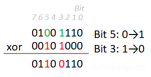
#define MASK1 0x28 // 0b00101000 unsigned char REG = 0x4E; // 0b10111110 REG = REG ^ MASK1; // REG is now 0x66 (01100110 in binary) - To toggle the 3rd bit of an 8-bit register:
#define BIT3_MASK 0x08 // 0b00001000 unsigned char REG = 0xA3; // 10100011 in binary REG = REG ^ BIT3_MASK; // REG is now 0xAB (10101011 in binary) REG = REG ^ BIT3_MASK; // REG is now 0xA3 (10100011 in binary) - To toggle the lamp connected to PB2, bit 2 of the Port B DATA register must be inverted.
The following expression shows how to invert bit 2:
PORTB->DATA = PORTB_>DATA ^ _BIT2;
// or
PORTB->DATA ^= _BIT2;
- Example: The other bits are unchanged, inverting on bits 5 and 3.
Set Multiple Bits Value
To set specific bits in a register to arbitrary values, you can follow a two-step process:
- Clear the bits you want to modify.
- Set the desired bits to the new values.
Example: Set reg[4:2] to (010)2
- Clear bits 4, 3, and 2.
- Use a bit-wise AND operation with a "mask 0" value that has 0s in the positions of the bits to clear and 1s elsewhere.
- Set bits 4, 3, and 2 to the value (010)₂.
- Use a bit-wise OR operation to set the bits to the desired value.
uint8_t  value = 0x02;   // or 0b010

// Clear bit 4, 3, and 2
reg &= ~(_BIT4 | _BIT3 | _BIT2);

// Set bit 4, 3, and 2 to the new value
reg |= (value << 2);
Or, we can combine the two steps into one statement as below:
uint8_t  value = 0x02;   // or 0b010

// Clear bits 4, 3, and 2; then set them to the new value
reg = (reg & ~(_BIT4 | _BIT3 | _BIT2)) | (value << 2);
This method ensures that only the specified bits are modified while other bits in the reg remain unchanged.
Checking bit value
So far, you have learned how to change bit values. However, suppose you want to determine whether the particular bit is set. The following test does not necessarily work:
#define _BIT2   0x04                // 0b00000100

if ( PORTB->DATA == _BIT2)          // no good - testing bit 2
This is because even if bit 2 in PORTB is set to 1, other bits might also be set to 1. The equality above is true only when bit 2 is the only bit set to 1.
The Bitwise-AND operator (&) can be used to check the bit state. First, use bitwise-AND to AND PB with a bitmask value (The corresponding bit in bitmask must be set to 1, leaving other bits to 0). This produces a value that is 0 in all the other bit positions because 0 AND any value is 0. Only the bits corresponding to the 1 is left unchanged because 1 AND any value is that value. Therefore, if the result is zero, then the bit was off. But, if the result is any other value, then the bit was on. Figure 8 illustrates how this operation works.
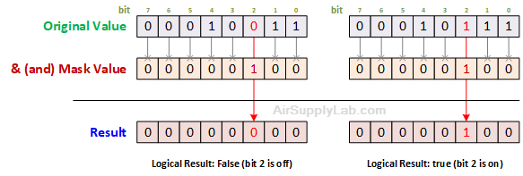 Figure 8: How an & (and) Mask Works
The proper test is this:
if ((PB & _BIT2) != 0) // testing if bit 2 equals 1 ?For one-bit testing, programmers often simplify this test to the following:
if (PB & _BIT2) // testing if bit 2 equals 1 ?if ((PB & _BIT2) == 0) // testing if bit 2 equals 0 ?For one-bit testing, programmers often simplify this test to the following:
if (!(PB & _BIT2)) // testing if bit 2 equals 0 ?For multiple-bit testing, you need to identify the correct value to compare with the result:
- Checking both PB0 & PB1 are 1
if ((PB & (_BIT0 | _BIT1)) == (_BIT0 | _BIT1)) // testing bit 2 and bit 0 (both are 1) - Checking both PB0 & PB1 are 0
if ((PB & (_BIT0 | _BIT1)) == 0)    // testing bit 2 and bit 0 (both are 0)
// or
if ( !(PB & (_BIT0 | _BIT1)))       // testing bit 2 and bit 0 (both are 0)
Reading a bit value
To read the current state of a pin into a variable, use the bit-wise AND operator to filter the corresponding bit. Since the pin state is a logic value, there are only two values, either logic 0 or logic 1, so the data type of the variable used to store the pin state can be set to a Boolean variable.
For example, the SW1 is connected to PB2. To read PB2 state into sw1 variable:
bool sw1;

sw1 = PORTB->DATA & _BIT2;
To check the sw1 state (connected on PB2):
if (sw1 == true){
.... // sw1 is logic 1
}

if (sw1 == false){
.... // sw1 is logic 0
}Summary:
- Mask 1: Used for checking, setting, or toggling a bit.
- Mask 0: Used for clearing a bit.
- Bit-wise AND (&): Used for checking or clearing a bit.
- Bit-wise OR (|): Used for setting a bit.
- Bit-wise XOR (^): Used for toggling a bit.
Bit-wise operators are essential tools in embedded programming for manipulating individual bits within registers. They provide efficient and precise control over hardware, enabling tasks such as setting, clearing, checking, and toggling specific bits. You can write more efficient and maintainable embedded code by understanding and utilizing these operators.
Useful Pre-Definition Mask 1 Values
In embedded systems, it is common to define masks for specific bits to facilitate operations like setting, clearing, or checking bits. Below are some pre-defined mask 1 values for an 16-bit register, which you can use for various bit manipulation tasks. Write the following definitions in a header file, like MyDefines.h. Then, include the file in your project.
#ifndef __MYDEFINES_H
#define _MYDEFINES_H

#define _BIT0   (1UL << 0 )         // 0b00000001 - Mask for bit 0
#define _BIT1   (1UL << 1 )         // 0b00000010 - Mask for bit 1
#define _BIT2   (1UL << 2 )         // 0b00000100 - Mask for bit 2
#define _BIT3   (1UL << 3 )         // 0b00001000 - Mask for bit 3
#define _BIT4   (1UL << 4 )         // 0b00010000 - Mask for bit 4
#define _BIT5   (1UL << 5 )         // 0b00100000 - Mask for bit 5
#define _BIT6   (1UL << 6 )         // 0b01000000 - Mask for bit 6
#define _BIT7   (1UL << 7 )         // 0b10000000 - Mask for bit 7
#define _BIT8   (1UL << 8 )         // 0b00000001_00000000 - Mask for bit 8
#define _BIT9   (1UL << 9 )         // 0b00000010_00000000 - Mask for bit 9
#define _BIT10  (1UL << 10)         // 0b00000100_00000000 - Mask for bit 10
#define _BIT11  (1UL << 11)         // 0b00001000_00000000 - Mask for bit 11
#define _BIT12  (1UL << 12)         // 0b00010000_00000000 - Mask for bit 12
#define _BIT13  (1UL << 13)         // 0b00100000_00000000 - Mask for bit 13
#define _BIT14  (1UL << 14)         // 0b01000000_00000000 - Mask for bit 14
#define _BIT15  (1UL << 15)         // 0b10000000_00000000 - Mask for bit 15

#endif
Example Usage:
- Setting a Bit:
PORTB = PORTB | _BIT2; // Set bit 2 of PORTB to 1 - Clearing a Bit:
PORTB = PORTB & ~BIT2; // Clear bit 2 of PORTB to 0 - Toggling a Bit:
PORTB = PORTB ^ _BIT2; // Toggle bit 2 of PORTB - Checking a Bit:
if (PORTB & _BIT2) {
    // Bit 2 of PORTB is set
} else {
    // Bit 2 of PORTB is not set
}
Summary:
Pre-defined mask values are useful for simplifying bit manipulation tasks in embedded systems. By defining masks for individual bits, you can easily perform operations like setting, clearing, toggling, and checking specific bits within a register.
Bit Access Functions
Bit Access Functions
Using functions to get or set a particular bit in a variable can improve code readability and maintainability in embedded systems programming. Below are examples of such functions:
Set Any Bit to Either 0 or 1
SetBit() function sets a particular bit to either 0 or 1.
Function Definition:
#include
#include

// var: 8-bit variable.
// bit: bit position to set, range is 0-7.
// b:   set bit to this, either 1 or 0

void SetBit(volatile uint8_t *var, uint8_t bit, bool b) {
    *var = (b) ?  ( *var |  (1 << bit)) :       // Set bit to 1
                  ( *var & ~(1 << bit)) ;       // Set bit to 0
}
//------------------------------------------------------------------------------
// var16: 16-bit variable.
// bit:   bit position to set, range is 0-15.
// b:     set bit to this, either 1 or 0

void SetBit16(volatile uint16_t *var16, uint8_t bit, bool b) {
    *var16 = (b) ? (*var16 |  (1UL << bit)) :   // Set bit to 1
                   (*var16 & ~(1UL << bit)) ;   // Set bit to 0
}
Usage Example:
volatile uint8_t data = 0x00;   // Example variable

SetBit(&data, 2, true);         // Set bit 2 of data to 1
SetBit(&data, 2, false)         // Set bit 2 of data to 0
Get the Value of a Particular bit in an Integer Variable
GetBit() returns the value of a specific bit in a variable.
Function Definition:
#include
#include

// var: 8-bit value.
// bit: bit position to set, range is 0-7.
bool GetBit(uint8_t var, uint8_t bit) {
    return (var >> bit) & 0x01;
}
//------------------------------------------------------------------------------
// var16: 16-bit value.
// bit:   bit position to set, range is 0-15.
bool GetBit16(uint16_t var16, uint8_t bit) {
    return (var16 >> bit) & 0x01;
}
Usage Example:
volatile uint8_t data = 0x04;           // Example variable (bit 2 is set)

boot bitValue = GetBit(data, 2);        // Get the value of bit 2, should be 1 (true)